
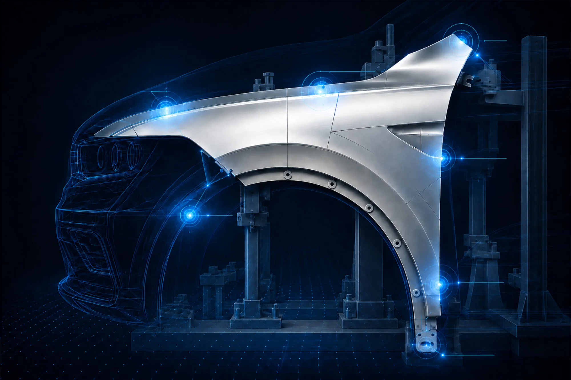
If the condition when the part is loose does not match its condition after installation
Flexible, thin-walled, or large-surface-area components may have a different geometry when exposed than they do once installed. The component’s own weight, material stresses, and specified fastening conditions influence its shape and position.
Traditional measurement concepts often simulate this condition using mechanical clamping devices. These must be designed, manufactured, and, if necessary, modified when changes are made.
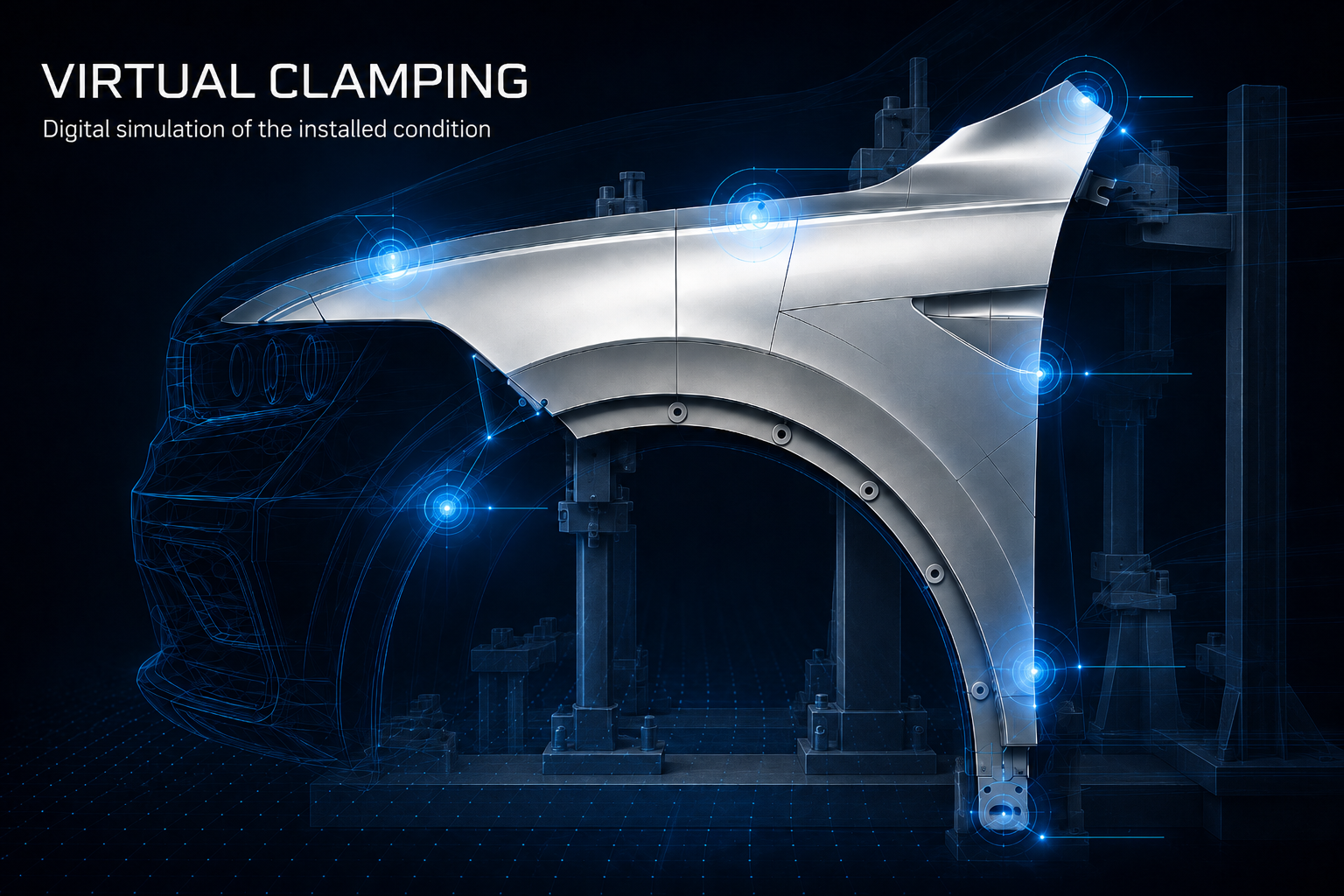
Virtual Clamping shifts this step to the digital analysis phase:First, the mounting and fastening conditions relevant to the subsequent installation are defined. The component is then scanned optically, with as few additional external influences as possible. Based on the measurement data and the previously defined boundary conditions, the future installation or clamping state is virtually simulated.
This is especially interesting when...
the uninstalled state does not correspond to the installed state
- Components that are flexible or have thin walls
- Variations and changes occur frequently
- Mechanical clamping techniques are very labor-intensive
Your Benefits with PROTOS-3D
Virtual Clamping with Expertise from the Very Beginning
We have been working intensively on virtual clamping since its early introduction, and today we combine measurement technology, FEM expertise, and our own PRAFSin-house development into an end-to-end process.
Experience dating back to the very beginning
Practical knowledge gained from several years of using virtual clamping.
In-House FEM Expertise
Experience with modeling, boundary conditions, and evaluation.
PRAFS developed in-house
Flexible component mounting can be optimally combined with Virtual Clamping.
End-to-End Process from a Single Source
From 3D scanning to virtual analysis.
From the Test Concept to Evaluation in-Service
Virtual Clamping uses the fully captured 3D geometry as the basis for a finite element analysis (FEA). The relevant support, fixation, and clamping conditions must be defined or known prior to measurement. The component is then optically captured under suitable conditions that minimize external influences as much as possible. Based on the measurement data and the previously defined boundary conditions, the resulting installation state is calculated virtually.
This allows the geometry to be evaluated not only in its freely measured state, but also under the conditions that are actually relevant to its subsequent function.
01
Define Boundary Conditions
Specify the mounting, support, clamping, and tension conditions before taking the measurement.
02
3D Scanning
Digitize the component visually and, as much as possible, free from additional external influences.
03
Virtual Clamping
Convert measurement data to the installed state using a FEM-based approach with the defined boundary conditions.
04
Perform a geometric analysis
Evaluate shape, location, and functionally relevant areas.
Less reliance on mechanical clamping methods.
Greater flexibility in analysis.
Specified Installation Conditions
The evaluation is based on the relevant installation condition rather than solely on the exposed component.
Less setup and changeover effort
Depending on the application, component-specific clamping concepts can be simplified, and changes can be incorporated digitally.
Reproducible basis for evaluation
Consistently defined boundary conditions improve the comparability and traceability of recurring evaluations.
What Virtual Clamping Reveals in the Analysis
Virtual clamping enables the geometric evaluation of a component under previously defined installation conditions. This allows for the assessment of deviations that would not be fully meaningful if evaluated solely in a free-standing state.
The focus is, for example, on shape and location, joints and transitions, local distortions, as well as connection and mating areas. Which characteristics are actually relevant depends on the specific function and inspection task.
SHAPE & POSITION · JOINTS · TRANSITIONS · SKEW · FIT ZONES
Virtual Clamping in conjunction with PRAFS
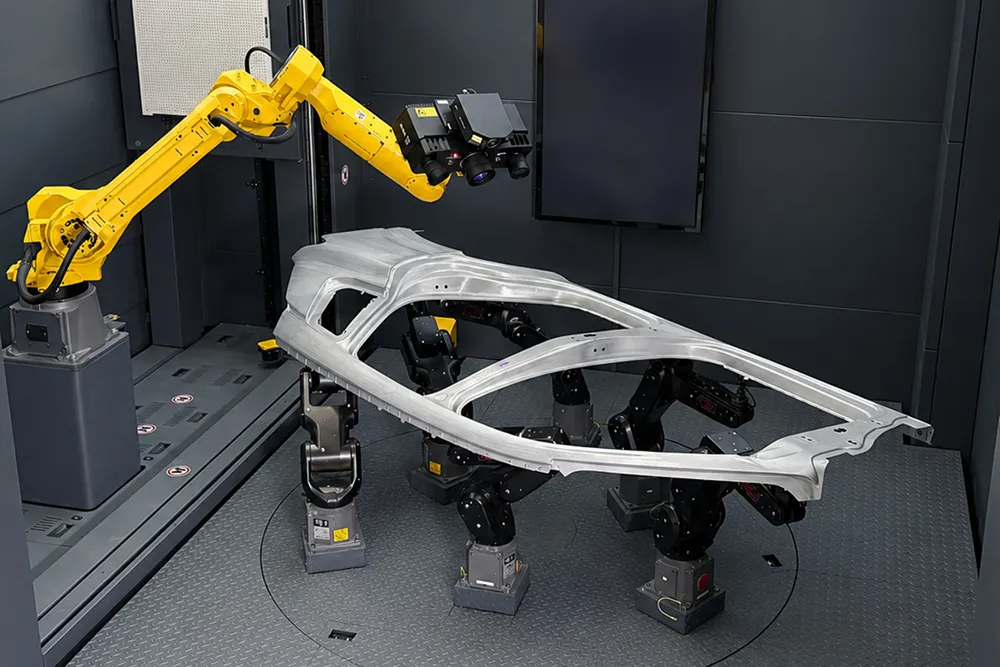
In conjunction with PRAFSPROTOS-3D , Virtual Clamping can be integrated into automated optical measurement processes. PRAFS handles the reproducible gripping and positioning of the component, thereby laying the foundation for complete 3D measurement.
Based on the previously defined boundary conditions, the desired installation state is then calculated by the software and evaluated geometrically.
In the case of recurring inspections and different component variants, this can help reduce the mechanical setup effort in particular.
Particularly useful for flexible components with many variations
Virtual clamping really comes into its own with thin-walled or large-surface-area components whose geometry is influenced by their installation conditions. Even with a wide variety of variants and short changeover cycles, digitally defined boundary conditions can reduce the effort required for component-specific clamping solutions.
Frequently Asked Questions About Virtual Clamping
What is virtual clamping?
Virtual clamping is a digital method used to simulate a defined clamping or installation condition of a component using FEM analysis based on 3D measurement data.
How does virtual voltage work?
Before the measurement, the relevant boundary conditions—such as supports, fixings, or clamping points—are defined. The component is then scanned. Based on the measurement data and the previously defined boundary conditions, a calculation is performed to determine how the component will behave in its intended installation state.
For which components is Virtual Clamping suitable?
Especially for flexible, thin-walled, or large-surface-area components, as well as for applications with a wide variety of variants or frequent changes.
Does virtual clamping replace every mechanical clamping device?
Not necessarily. Whether a device can be scaled down or completely replaced depends on the component geometry, material properties, boundary conditions, and the specific testing task.
What role does PRAFS play in the process?
PRAFS ensures that the component is consistently mounted and positioned during 3D optical measurement. Virtual Clamping supplements this process by digitally representing the component's future installed state.
Is it possible to conduct feasibility studies before implementation?
Yes. Before implementation, it is possible to verify whether component geometry, material behavior, boundary conditions, and quality requirements can be reliably modeled using Virtual Clamping.
Evaluate components based on how they will be used later
Virtual Clamping extends optical 3D metrology by enabling the evaluation of components not only in their free-state but also under defined installation conditions.
Particularly when dealing with flexible components, a wide variety of variants, and recurring inspection tasks, this results in a practical approach that can reduce mechanical effort and bring the geometric evaluation closer to the actual installation conditions.
Would you like to know if virtual clamping is suitable for your components?
We assess the technical feasibility based on your specific measurement task.