
Reverse Engineering
From scan to model
Reverse engineering refers to the reverse design process. A data model (CAD surface/volume model) is created over the real component.
In the absence of design data or drawings, this is one of the methods used. Reverse engineering is also used for modified components or tools that no longer correspond to the original design. With the help of modern, high-resolution 3D fringe projektion scanners, the data basis for reverse engineering is laid. Data acquisition is contact-free, so even sensitive components can be measured without the risk of damage.
Examples of reverse engineering applications
- Modifications of component geometries
- Missing construction data
- Form finding via manual design methods, e.g. model making, design
- Unique pieces or irreplaceable works of art
- Immediate use of CAD surfaces for subsequent processes
Principle procedure for reconstruction of modified or damaged mold components

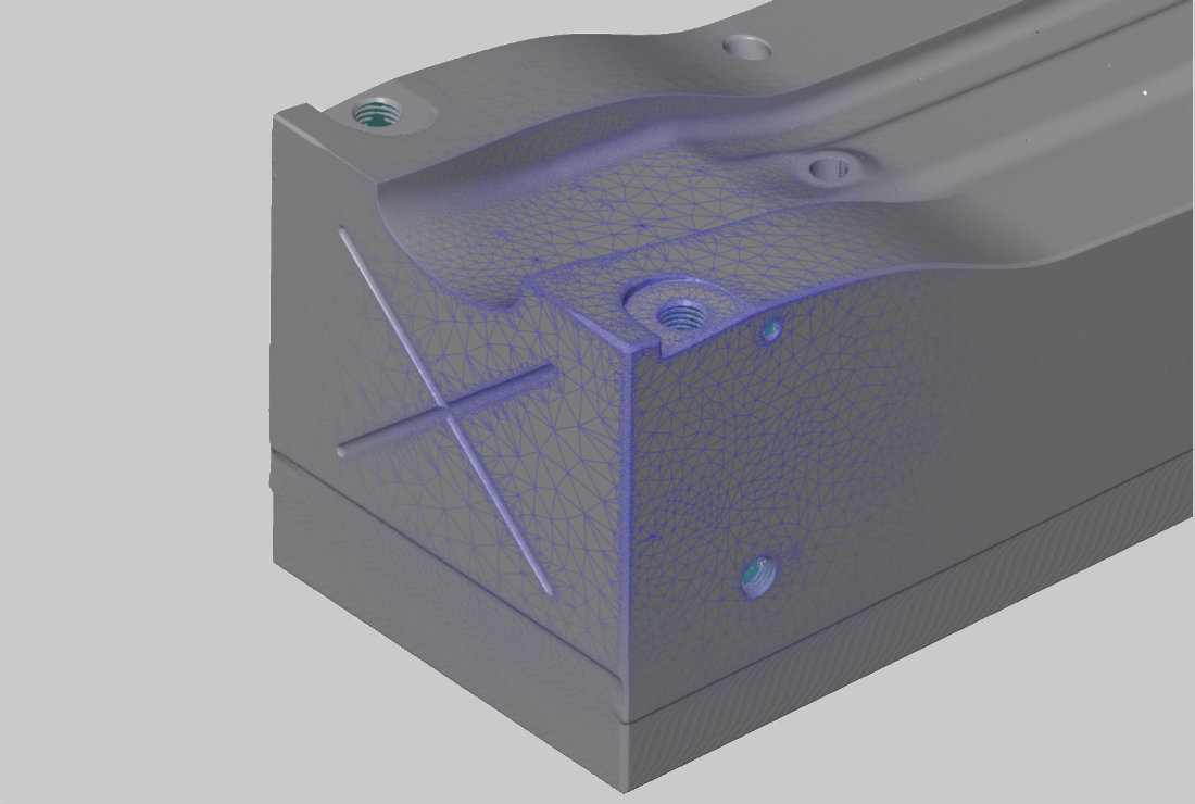
Data acquisition
After digitizing the component using ATOS, a 3D model (stl data set) is generated and output.
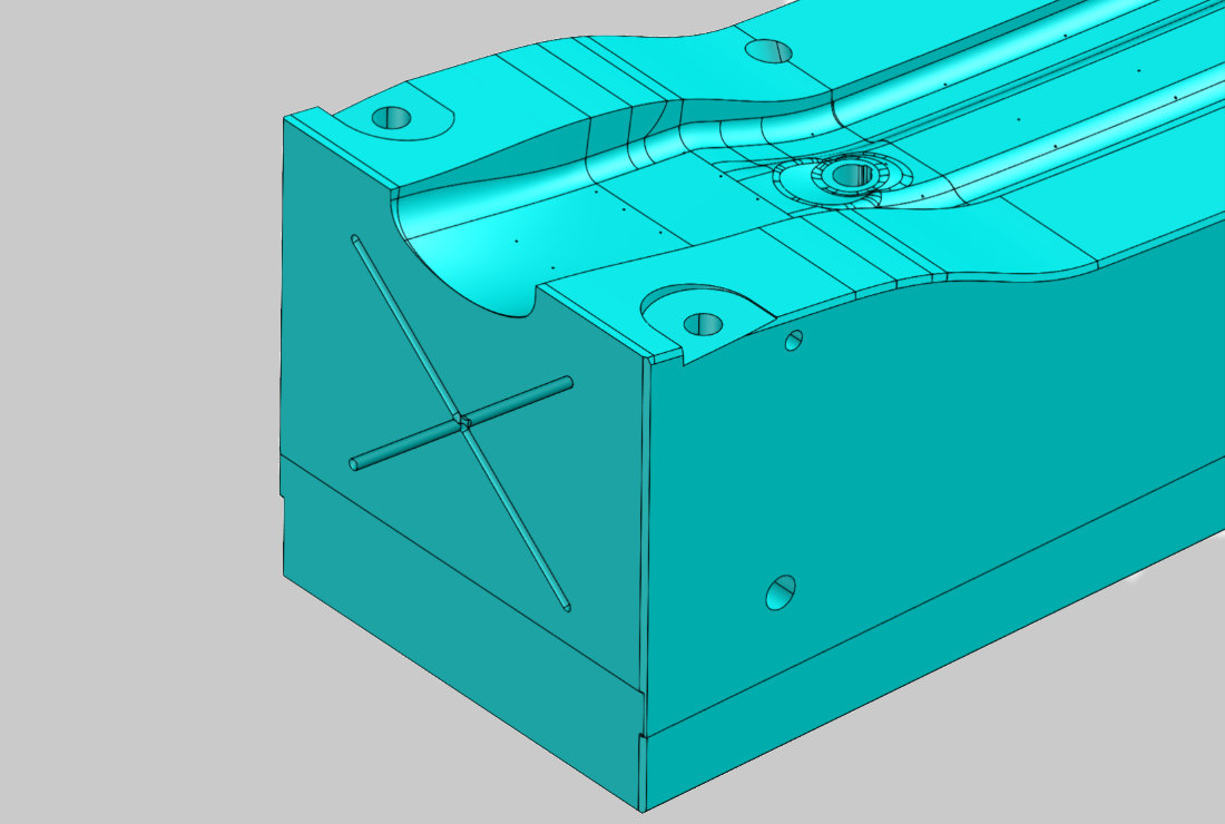
Generation of regular geometries
In this process step, the basic geometries are generated in the CAD software. These basic geometries ( regular geometries) are used for the base surface, the side surfaces, holes and pockets. The information is derived from the design intent and based on the 3D mesh.
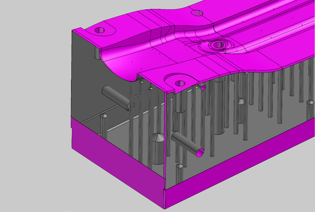
Creation of freeform surfaces
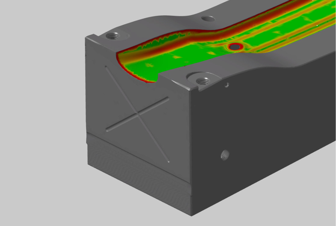
In order to reverse engineer freeform surfaces, the stl data is visualized using a function for ``curvature-based analysis``. Here, the curvature ratios of the surface (tangential transitions and curvature changes) are displayed. The result is a surface model with clean surfaces and radius transitions. From the surface model, individual surfaces and the sliding degree are controlled via tolerance specifications. These surfaces can have any number of boundary curves.
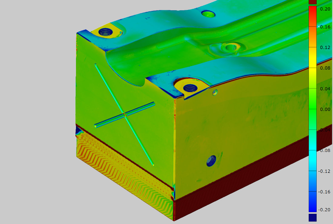
Quality control
The intermediate and final results are evaluated via a nominal/actual comparison and, if necessary, manually reworked.
Completion of the reconstructed surface model
The freeform parts are cut with the regular geometry parts. All bore axes, thread markings and fits are incorporated. You can go straight into production after the data has been delivered.
Questions?
We analyse.
You profit.
How can we support you? Contact us and we will get back to you as soon as possible.
Sorry, no posts matched your criteria.